
Industrial Equipment & Technical Diagnostic Knowledge Test FAQ
Comprehensive technical diagnostics, repair protocols, and situational failure analysis across horizontal grinders, screening trommels, mulch colorizers, heavy yard loaders, and pneumatic blower fleets.
1. Horizontal Grinders, Tub Grinders & Chippers
Verify all emergency stop (E-stop) cables and buttons function properly. Check hydraulic fluid sight glasses and reservoir temps. Inspect rotor bearings for proper grease purge (avoiding over-greasing which blows seals). Check drive belts/couplings for wear or misalignment. Ensure grate locks and access doors are fully pinned and secured. Check engine oil, coolant, and air filter restriction indicators.
Check against OEM wear gauges or measurement thresholds (e.g., maximum allowable material loss from the cutting edge/carbide insert). If the base metal is exposed behind the carbide or the tip is rounded past its cutting radius, it requires hardfacing or replacement. Running worn hammers destroys screening efficiency and causes severe vibration.
Lockout/tagout (LOTO) the machine completely. Let the heavy rotor come to a full stop (never rush this; flywheels hold massive kinetic energy). Open the screen cradle hydraulic doors. Use a hydraulic extraction tool or overhead hoist to slide out old grates. Inspect screen cage slots for wear, slide in the new specified hole-size grates, lock them securely, and verify proper clearance before closing doors.
The anvil acts as the shear point against the rotating hammers. Proper gap (typically specified by the OEM, e.g., 3/8" to 3/4" depending on application) ensures clean shearing of wood fiber without metal-to-metal contact. If the gap is too wide, material wedges and reduces output; if too tight, hammers strike the anvil, causing catastrophic shaft bending, bearing failure, or rotor destruction.
Look for cupping, rounding of the leading edge, cracking, or severe impact indentations. A compromised slug bar allows un-shredded material to bounce back into the rotor path, causing bridging, erratic feeding, and excessive shock loads on the driveshaft.
Hook up hydraulic pressure gauges to the feed circuit test ports. Check main relief valve setting. If pressure spikes and relief chatters prematurely, the relief is set too low or sticking. If pressure remains low, check for pump displacement stroke failure, worn pump rotating groups, or internal bypass in the feed drive motor.
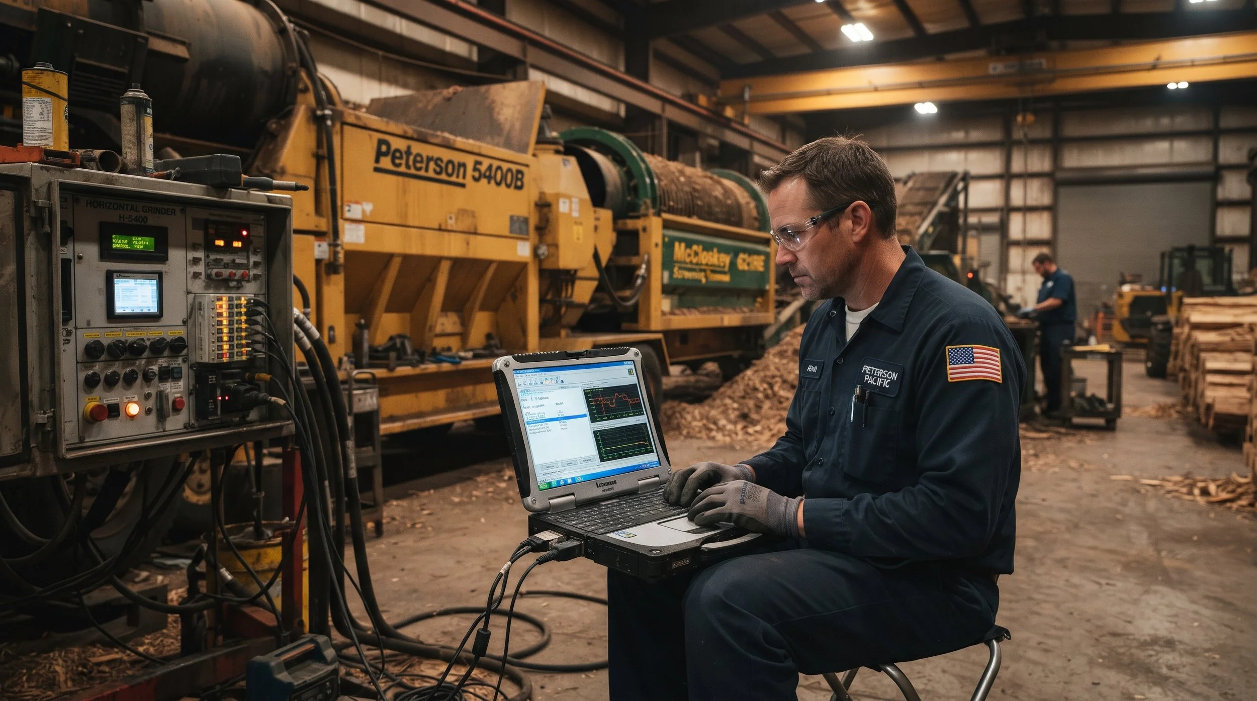
Connect diagnostic software (e.g., CAT ET or Service Advisor) or use a digital multimeter. Verify the magnetic pickup (MPU) or CAN bus engine RPM signal. Check the rotor speed sensor gap and signal integrity. If the engine drops below the governor threshold (e.g., dropping past 1,800 RPM), the ECM commands the infeed to reverse/stop to let the engine recover. A failing speed sensor or loose connection causes false triggers.
Use an infrared thermometer across the hydraulic oil cooler core to check for blocked tubes or uneven cooling (indicating airflow restrictions or internal clogging). Check if the thermal bypass valve is stuck open (routing oil around the cooler). Check case drain flows on the main pumps and motors—excessive case drain flow indicates internal pump/motor wear dumping high-pressure oil directly back to the tank as heat.
1. Lockout machine and allow complete rotor stop. 2. Visually inspect all hammers, bolts, and retainers for missing or sheared parts. 3. Check rotor shaft runout with a dial indicator. 4. Inspect main pillow-block bearings for excessive play, discoloration (heat), or metallic flakes in grease. 5. Check for structural cracks in the rotor disc/drum plates using dye penetrant or magnetic particle inspection if necessary. Never run a vibrating rotor; it will destroy the frame and bearings.
1. Check coolant level and radiator core for heavy wood-dust packing (requires high-pressure air/water wash). 2. Verify fan clutch engagement (air-actuated or viscous). 3. Check thermostat operation with an infrared gun. 4. Inspect EGR cooler for internal leaks or fouling. 5. Connect diagnostic software to check boost pressure, exhaust gas temperatures (EGT), and fuel rail pressures.
1. Complete LOTO and bleed all stored hydraulic and pneumatic energy. 2. Engage mechanical rotor locking pins. 3. Use a slow-speed reversing tool or safe auxiliary bar to back the rotor out of the jam (never use direct starter engagement). 4. Inspect rotor shafts, drive belts/fluid couplings, and gearbox for torsional twisting or shear pin failure. 5. Clear all jammed material manually before unlocking and test-firing at idle.
2. Screening, Trommels & Separation Systems
Inspect welded seams, ring frames, and mesh panels for stress cracks, worn wire mesh holes, and loose bolting. Look for material buildup in corners that can throw the drum out of balance.
Clean grease zerk fittings thoroughly before pumping grease to prevent injecting contaminants. Pump fresh grease slowly while the bearing is rotating (if safe) until clean grease purges from the seal lip, flushing out abrasive wood dust and moisture.
Always adjust tracking while the belt is running under no load first, then test under load. Adjust the tensioning bolts equally on both sides to maintain tension, then adjust the tracking idlers or snubber rollers on the side the belt is pulling toward (i.e., if the belt drifts right, advance the right side forward or back the left side off slightly).
Check hydraulic pressure at the inlet of the drum drive motor. If high pressure is present and the motor stalls/doesn't turn, the hydraulic motor or planetary gearbox is mechanically seized. If zero pressure is present, trace back to the directional control valve, solenoid coil power supply, or upstream priority flow divider.
Check the condition and adjustment of the drum cleaning brushes or rubber tensioner knockers. If moisture content in the compost/mulch is too high, material coats the screen openings. Adjust feed rate, check for worn screen panels, or switch to a slightly larger mesh size if processing wet seasonal material.
1. LOTO the unit and drain remaining gear oil into a clean pan to inspect for metal shavings. 2. Disconnect hydraulic lines and plug ports. 3. Unbolt the hydraulic motor, supporting it properly. 4. Unbolt and hoist the planetary gearbox out of the trunnion mount. 5. Install the replacement gearbox, ensuring proper spline engagement and alignment with the bull gear/ring gear to prevent premature tooth wear. Refill with specified synthetic gear oil.
Measure diagonal frame dimensions to check for squareness. Check trunnion support roller heights using precision shims and a straight edge or laser level. Adjust eccentric roller shafts or add/remove shims under roller pedestals so the drum rides evenly centered on grooved rollers without binding against thrust rollers.
3. Mulch Coloring & Processing Plants
Flush lines thoroughly with clean water to clear any dried pigment residue. Check all inline strainers and nozzle tips for clogs. In freezing climates, ensure lines are blown out with compressed air or filled with an approved eco-friendly anti-freeze solution to prevent cracked PVC plumbing and pump housings.
Inspect air supply lubricators and regulators (for AODD pumps). Check diaphragm bolts for proper torque. Inspect ball checks and seats for wear or debris buildup that causes loss of prime and low output volume.
Check spray bar pressure gauges. Clean plugged or worn spray nozzles. Inspect internal mixing paddles/augers for wear or broken blades that fail to tumble the mulch adequately through the colorant mist. Verify chemical flow meter calibration against timed bucket tests.
Test DC/AC voltage to electronic solenoid valves. Check for stuck or scaled-up flow control valves. Recalibrate the PLC control panel input parameters matching water-to-colorant ratios. Clean magnetic or turbine flow meters of fibrous buildup.
Disconnect power (LOTO). Try to rotate the pump shaft manually to check for internal seizing caused by hardened dried colorant. If free, check motor winding resistance (ohm test) and insulation breakdown (megger test). Check VFD output parameters, ramp-up times, and thermal overload settings to ensure proper sizing.
1. Flood the mixing drum and auger trough with warm water and industrial solvent/degreaser designed to break down iron oxide/carbon pigments. 2. Allow it to soak, then manually scrape hardened deposits. 3. Disassemble paddle shaft packing glands and bearings. 4. Inspect paddle timing marks before reassembly to ensure opposing paddles do not strike each other during rotation.
4. Yard Loaders, Material Handlers & Heavy Equipment
Open side gull-wing doors and core swing-out frames. Use compressed air (regulated) or a specialized fin-cleaning wand with low-pressure hot water/solvent to blow wood dust outward from the engine side through the radiator, hydraulic oil cooler, transmission cooler, and charge air cooler fins. Never use high-pressure washers directly perpendicular to fragile aluminum fins.
Grease all loader linkage pins (bucket pins, lift arms, tilt cylinders, steering cylinders) daily. High-load pins require fresh grease to force out grit. Check engine oil, transmission oil, hydraulic oil sight glasses, and axle fluid levels.
Control Valve Spool: If internal spool scoring allows oil to bypass to tank, warm up oil, raise bucket, shut off engine, and move levers—if cylinder drift changes, it's spool/valve leakage. Cylinder Seal: Perform a cylinder bypass test (drop test) by raising the loader arms, disconnecting and plugging the rod-end hydraulic line, and observing if oil pours out of the open port when weight is applied. If so, internal piston seals are blown.
Install hydraulic pressure gauges into designated transmission test ports (main system pressure, clutch pack pressures). Compare cold vs. hot readings against OEM spec. Low pressure when hot indicates worn transmission pump, excessive internal clutch pack clearance, blocked transmission filter, or failing seals.
Connect diagnostic software to read active soot load percentage and fault codes. If soot is below the hard-shutdown threshold, initiate a stationary service regen via diagnostic laptop. Inspect DPF differential pressure sensor lines for plugging or melting. Check fuel injectors and EGR valve for carbon fouling causing excessive soot production.
1. Drain axle oil and inspect magnetic drain plugs for excessive metal chunks or needle bearings. 2. Block machine safely, hoist axle, and pull planetary hub covers. 3. Inspect sun gears, planet gears, and carrier housing. 4. If failure extends to the differential, drop the axle assembly, split the housing, and inspect the ring and pinion gear tooth patterns and differential spider gears.
1. Drain entire hydraulic system and flush reservoirs. 2. Replace all hydraulic filters (pressure, return, case drain). 3. Remove failed pump and thoroughly flush all suction and discharge lines. 4. Install new pump, fill case with clean filtered hydraulic oil before startup to prevent dry running. 5. Bleed pump case, start machine at low idle, and cycle functions slowly without loading.
Check J1939 data link resistance across CAN-High and CAN-Low lines with a multimeter (should read approximately 60 ohms with batteries disconnected, indicating two 120-ohm terminating resistors in the network). Trace harness for chafing, water intrusion in weather-pack connectors, or a failed terminating resistor.
5. Pneumatic Blower Trucks & Transport Fleet
Inspect rotor vane tips for wear against the housing tolerances (excessive gap allows air loss and blowing efficiency drop). Check shaft seals, drive chains/gearboxes, and grease fittings. Ensure no foreign debris or metal objects are trapped in the pocket feeders.
Inspect PTO driveline universal joints for play, grease them, and check shear pins or electronic torque limiters. Check auxiliary engine oil, fuel filters, and cooling belts if the blower runs off a dedicated auxiliary deck engine.
Inspect hose walls for pinholes, thinning, or cracking from dragging across concrete and rough terrain. Ensure cam-lock quick-connect fittings have secure safety pins and fresh rubber gaskets to maintain airtight pneumatic pressure seals.
Check for worn rotary airlock rotor tips (allowing air to blow backward instead of pushing material). Inspect blower intake air filters. Check blower belt tension or hydraulic drive pressure. Check all hose connections and quick-connect gaskets for air leaks (hissing sounds during operation).
Check transmission PTO air supply pressure using a gauge. Inspect clutch pack solenoid valves and wiring. If pneumatic or hydraulic pressure is within spec but the clutch slips under load, the internal friction discs are worn out and require PTO rebuild or replacement.
1. Disconnect drive chain/gearbox and unbolt end plates. 2. Extract rotor assembly from housing. 3. Inspect housing bore for scoring; machine or replace if out of tolerance. 4. Install new rotor vanes/tips, setting precise radial and axial clearances per manufacturer specs using feeler gauges to ensure zero binding while minimizing air blow-by.
1. Build air system using shop air if necessary. 2. Spray soapy water on compressor governor, purge valve, air dryer cartridge, and glad hands. 3. Check unloader valve operation. If air dryer desiccant bag has broken down, oil and moisture contaminate the entire system, requiring flushing and replacement of valves and brake chambers.
Connect diagnostic software to check DEF dosing pressure and NOx sensor ppm readings. Inspect DEF injector nozzle for crystalline urea buildup ("white crust"). Clean or replace injector, check DEF tank fluid concentration with a refractometer (should be 32.5% urea), and inspect heated lines and DEF pump module filters.
6. Cross-Functional & Situational Problem Solving
Check main ECM power relays and fuse blocks for corrosion or thermal degradation. Inspect ignition switch and emergency stop circuit loop wiring for intermittent grounding. Check battery cables, main ground studs on the engine block, and alternator output stability.
Stop operating immediately. Drain entire hydraulic tank, cylinders, and lines. Flush system with flushing oil or low-viscosity hydraulic oil. Replace all return and pressure filter elements multiple times after short operational cycles. Universal tractor fluid contains friction modifiers that ruin high-pressure piston pumps and destroy brake/clutch disc material in planetary hubs.
Prioritize safety first (hazard lights, cones, traffic positioning). Triage by impact: secure the highway roadside repair using emergency mobile service truck protocols (caging brakes or replacing airline), and coordinate with the yard crew to secure the grinder in a safe LOTO state until morning or dispatch a night mobile mechanic if production deadlines demand immediate turnaround.
1. Disconnect battery negative terminals (or master battery disconnect). 2. Disconnect ECM/TCM computer harness plugs completely. 3. Clamp the welding ground cable as close as possible to the exact spot being welded (never allow current to bridge across hydraulic cylinders, pivot bearings, or electronic sensors).
Misalignment: Uneven wear on bearing races. Over-greasing: Blown grease seals, high internal pressure. Under-greasing: Heat discoloration, dry metal-on-metal scoring. Excessive tension: Premature axial load failure. Measure bearing temperature and shaft vibration with a vibration pen before teardown.
1. Properly support loader arms and relieve all hydraulic pressure. 2. Disconnect lines and plug ports. 3. Remove cylinder from machine and mount in a clean hydraulic bench vise. 4. Unscrew gland nut, pull rod assembly out carefully. 5. Inspect rod for scoring/pitting and barrel for scoring. 6. Replace piston seals, wear rings, and gland wiper seals using proper installation cones to prevent stretching. Reassemble and torque to spec.
Disconnect motor leads from VFD. Perform a megger test (insulation resistance test) on the motor windings to ground. Check phase-to-phase winding resistance balance with a digital multimeter. If motor checks out healthy, review VFD parameter settings (accel/decel times, current limits, boost settings) or check for mechanical binding in the auger trough causing excessive starting torque.
A robust PM program includes: Daily operator walk-arounds and greasing; Weekly filter checks, belt tensioning, and wear-plate inspections; Monthly oil sampling (spectrochemical analysis); and Quarterly comprehensive hydraulic fluid testing, structural crack inspections, and calibration checks. Track all work orders in a computerized maintenance management system (CMMS).
1. Notify all operators. 2. Shut down engine/power source. 3. Apply padlocks and tags to main battery disconnect and ignition. 4. Relieve stored hydraulic pressure by cycling joysticks/valves. 5. Engage mechanical rotor/drum locking pins. 6. Verify zero energy state before entering chamber.
Inspect worn hammers for impact vs. abrasion wear patterns. Check for tramp metal contamination (hidden rebar or steel in wood waste). Verify correct hammer alloy/hardness selection. Check rotor RPM—running too fast accelerates abrasive wear, while running too slow causes high impact shock. Verify anvil gap setting.
Drain fuel tank water traps and check bottom samples for microbial slime ("algae") or free water. Replace primary and secondary fuel filters. Treat bulk storage tanks with biocide and fuel stabilizer. If contamination is severe, pump out and polish the bulk storage tank.
Implement a dedicated night-shift maintenance crew (e.g., operating from 6:00 PM to 4:00 AM) to perform routine wear-part hardfacing, screen changes, conveyor belt vulcanization/splices, and heavy component swaps, leaving daytime hours 100% free for uninterrupted production and rapid response minor adjustments.